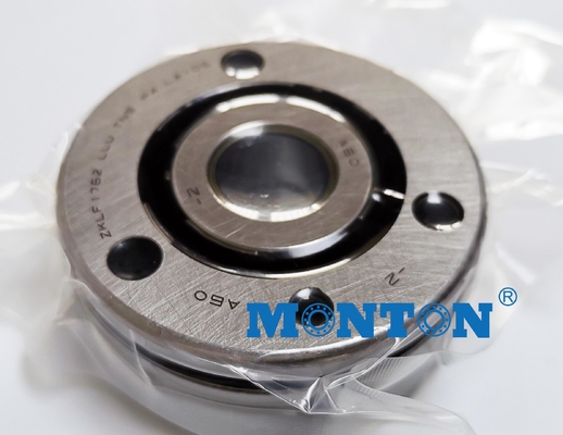
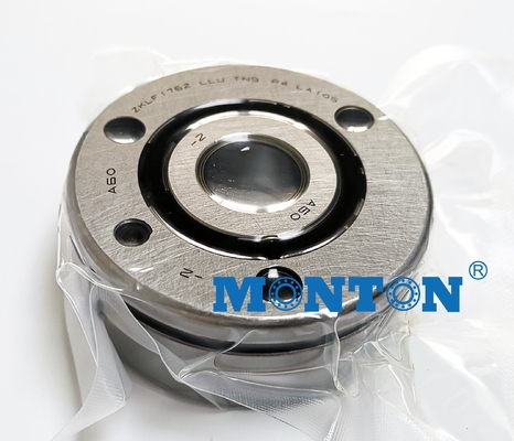
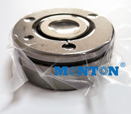
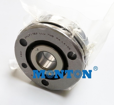
d | 15 mm | Tolerance: 0/-0,01 |
D | 60 mm | Tolerance: 0/-0,013 |
B | 25 mm | Tolerance: 0/-0,25 |
M6 | Threaded connector for lubrication | |
60 ° | Contact angle | |
M6 | Fixing screws to DIN EN ISO 4762 10.9 Screws not included in scope of delivery. Tightening torque according to manufacturer’s data. |
|
b | 3 mm | |
Da max | 35 mm | |
d1 | 28 mm | |
d2 | 6,8 mm | |
da min | 20 mm | |
I | 17 mm | |
J | 46 mm | |
na x ta | 3 x 120° | Fixing screws to DIN EN ISO 4762 10.9 Screws not included in scope of delivery. Tightening torque according to manufacturer’s data. Number of holes in adjacent construction corresponds to n a. |
n x t | 3 x 120° | Pitch |
r1 min | 0,6 mm | |
rmin | 0,3 mm | |
t1 | 0,1 mm |
m | 0,43 kg | ≈ Mass |
Ca | 17900 N | Basic dynamic load rating, axial |
C0a | 28000 N | Basic static load rating, axial |
Cua | 1280 N | Fatigue limit load, axial |
nG Fett | 8200 1/min | Limiting speed for grease lubrication |
nϑ | 3500 1/min | Thermally safe operating speed |
MRL | 0,2 Nm | Bearing frictional torque |
caL | 400 N/µm | Axial rigidity |
ckL | 65 Nm/mrad | Tilting rigidity |
Mm | 0,102 kg * cm^2 | Mass moment of inertia for rotating inner ring |
5 µm | Axial runout The axial runout data for screw drive bearing arrangements are based on the rotating inner ring. |
|
ZM15 | Recommended INA precision locknuts with radial clamping The recommended INA precision locknuts are not included in the scope of delivery and must be ordered separately. |
|
AM15 | Recommended INA precision locknuts with axial clamping The recommended INA precision locknuts are not included in the scope of delivery and must be ordered separately. |
|
MA | 10 Nm | Tightening torque Only valid in conjunction with INA precision locknuts. Observe the guidelines on locating/locating bearing arrangements. |
5484 N | Requisite locknut force, axial The requisite axial locknut force must be observed when using other locknuts. |
Here below is the exact bearing codes information:
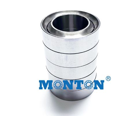
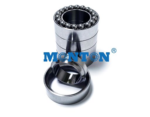
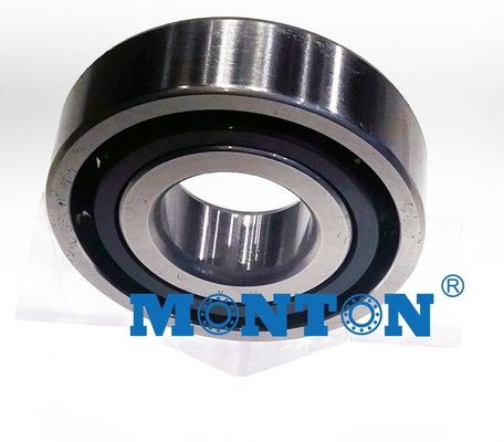
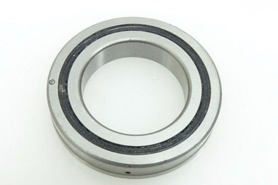
Angular contact ball bearings have raceways in the inner and outer rings that are displaced with respect to each other in the direction of the bearing axis, which means that they are designed to accommodate combined loads, i.e. simultaneously supporting radial and axial loads.The axial load carrying capacity of angular contact ball bearings increases with increasing contact angle. The contact angle α is defined as the angle between the line joining the points of contact of the ball and the raceways in the radial plane, along which the load is transmitted from one raceway to another, and a line perpendicular to the bearing axis.Retainers are made of brass ,synthetic resin of others subject to individual bearing features and application conditions.
Designation | Mass | Dimensions | Dimensions | t | Setscrew | Basic Load Ratings | Limiting | |||||||||||
d | D | B | d1 | D1 | r | r1 | J | d2 | b | l | Cr | Cor | Speed | |||||
-0.25 | min. | min. | min. | min. | min. | spec | amount | Dynamic | Static | grease | ||||||||
Kg | mm | mm | Q'ty×t | kN | Rpm | |||||||||||||
ZKLF 1255.2RS | 0.37 | 12 | 55 | 25 | 25 | 33.5 | 0.3 | 0.6 | 42 | 6.5 | 3 | 17 | 3×120° | M6 | 3 | 17 | 24.7 | 3800 |
ZKLF 1255.2Z | 0.37 | 12 | 55 | 25 | 25 | 33.5 | 0.3 | 0.6 | 42 | 6.5 | 3 | 17 | 3×120° | M6 | 3 | 17 | 24.7 | 7600 |
ZKLF 1560.2RS | 0.43 | 15 | 60 | 25 | 28 | 36 | 0.3 | 0.6 | 46 | 6.5 | 3 | 17 | 3×120° | M6 | 3 | 17.9 | 28 | 3500 |
ZKLF 1560.2Z | 0.43 | 15 | 60 | 25 | 23 | 12 | 0.3 | 0.6 | 46 | 6.5 | 3 | 17 | 3×120° | M6 | 3 | 17.9 | 28 | 7000 |
ZKLF 1762.2RS | 0.45 | 17 | 62 | 25 | 23 | 12 | 0.3 | 0.6 | 48 | 6.5 | 3 | 17 | 3×120° | M6 | 3 | 18.8 | 31 | 3300 |
ZKLF 1762.2Z | 0.45 | 17 | 62 | 25 | 25 | 14 | 0.3 | 0.6 | 48 | 6.5 | 3 | 17 | 3×120° | M6 | 3 | 18.8 | 31 | 6600 |
ZKLF 2068.2RS | 0.61 | 20 | 68 | 28 | 25 | 14 | 0.3 | 0.6 | 53 | 6.5 | 3 | 19 | 4×90° | M6 | 4 | 26 | 47 | 3000 |
ZKLF 2068.2Z | 0.61 | 20 | 68 | 28 | 30 | 16 | 0.3 | 0.6 | 53 | 6.5 | 3 | 19 | 4×90° | M6 | 4 | 26 | 47 | 5400 |
ZKLF 2575.2RS | 0.72 | 25 | 75 | 28 | 30 | 16 | 0.3 | 0.6 | 58 | 6.5 | 3 | 19 | 4×90° | M6 | 4 | 27.5 | 55 | 2600 |
ZKLF 2575.2Z | 0.72 | 25 | 75 | 28 | 32 | 20 | 0.3 | 0.6 | 58 | 6.5 | 3 | 19 | 4×90° | M6 | 4 | 27.5 | 55 | 4700 |
ZKLF 3080.2RS | 0.78 | 30 | 80 | 28 | 32 | 20 | 0.3 | 0.6 | 63 | 6.5 | 3 | 19 | 6×60° | M6 | 6 | 29 | 64 | 2200 |
ZKLF 3080.2Z | 0.78 | 30 | 80 | 28 | 34 | 23 | 0.3 | 0.6 | 63 | 6.5 | 3 | 19 | 6×60° | M6 | 6 | 29 | 64 | 4300 |
ZKLF 3590.2RS | 1.13 | 35 | 90 | 34 | 34 | 23 | 0.3 | 0.6 | 75 | 8.5 | 3 | 25 | 4×90° | M8 | 4 | 41 | 89 | 2000 |
ZKLF 3590.2Z | 1.13 | 35 | 90 | 34 | 40 | 25 | 0.3 | 0.6 | 75 | 8.5 | 3 | 25 | 4×90° | M8 | 4 | 41 | 89 | 3800 |
ZKLF 40100.2RS | 1.46 | 40 | 100 | 34 | 40 | 25 | 0.3 | 0.6 | 80 | 8.5 | 3 | 25 | 4×90° | M8 | 4 | 43 | 101 | 1800 |
ZKLF 40100.2Z | 1.46 | 40 | 100 | 34 | 45 | 32 | 0.3 | 0.6 | 80 | 8.5 | 3 | 25 | 4×90° | M8 | 4 | 43 | 101 | 3300 |
ZKLF 50115.2RS | 1.86 | 50 | 115 | 34 | 45 | 32 | 0.3 | 0.6 | 94 | 8.5 | 3 | 25 | 6×60° | M8 | 6 | 46.5 | 126 | 1500 |
ZKLF 50115.2Z | 1.86 | 50 | 115 | 34 | 50 | 40 | 0.3 | 0.6 | 94 | 8.5 | 3 | 25 | 6×60° | M8 | 6 | 46.5 | 126 | 3000 |
ZKLF 60145.2Z | 4.3 | 60 | 145 | 45 | 50 | 40 | 0.3 | 0.6 | 120 | 8.5 | 3 | 35 | 6×60° | M8 | 8 | 84 | 214 | 3000 |
ZKLF 70155.2Z | 4.9 | 70 | 155 | 45 | 59 | 45 | 0.3 | 0.6 | 130 | 8.5 | 3 | 35 | 8×45° | M8 | 8 | 88 | 241 | 2800 |
ZKLF 80165.2Z | 5.3 | 80 | 165 | 45 | 59 | 45 | 0.3 | 0.6 | 140 | 8.5 | 3 | 35 | 8×45° | M8 | 8 | 91 | 265 | 2700 |
ZKLF 90190.2Z | 8.7 | 90 | 190 | 55 | 64 | 50 | 0.3 | 0.6 | 165 | 10.5 | 3 | 45 | 8×45° | M10 | 8 | 135 | 395 | 2300 |
ZKLF 100200.2Z | 9.3 | 100 | 200 | 55 | 64 | 50 | 0.3 | 0.6 | 175 | 10.5 | 3 | 45 | 8×45° | M10 | 8 | 140 | 435 | 2150 |